Multicast Scoping — Solution Analysis & EVE-NG Lab Guide
ROUTING TCP/IP, VOLUME 2 · CHAPTER 7 · CONFIGURATION EXERCISE 1
Exercise source: Fig. 7-33 Network Topology for Configuration Exercise 1 · Target platform: EVE-NG (Cisco IOL / IOLL2) · Companion file: multicast-lab-topology.svg · Prepared: 2026-10-01
Contents
- The Exercise
- Solution Analysis — two scoping tools, and why boundary wins
- EVE-NG Lab Design — topology, images, cabling and addressing
- Complete Node Configurations (paste-ready)
- Lab Procedure (three acts) and Verification
- Troubleshooting Notes
- One-Page Summary
1 The Exercise
A company is implementing two multicast-based applications. Two Class D addresses have been assigned: 239.65.10.10 and 239.193.10.10. Requirement: the multicast traffic must be restrained within the boundaries of the campus — other branches and the core must not be transit.
- a. Explain how to restrain the multicast traffic for these two applications from flowing all around the network.
- b. Explain why these two IP addresses are not the best choices.
2 Solution Analysis
2.1 What the question is really about
The fundamental difference between multicast and unicast: a unicast packet is one copy headed for one destination, whereas in multicast the source sends one packet and the router replicates it out every outgoing interface. Forwarding depends on (S,G) / (*,G) state, and that state is built by PIM (dense mode flood-and-prune, or sparse mode trees toward the RP / the source).
So “multicast leaking out of the campus” is not a plain ACL problem — the real issue is that forwarding state gets built toward the core. There are only two kinds of interception point: stop the state and the packets at the boundary interface, or keep the traffic from ever qualifying to go there (relying on properties of the traffic itself — TTL — or on address semantics). IOS offers two classic tools for exactly this: TTL scoping and administrative scoping (the multicast boundary).
2.2 The two tools compared
| TTL threshold | Multicast boundary | |
|---|---|---|
| Config | ip multicast ttl-threshold <1-255> |
ip multicast boundary <ACL> [out|in] |
| Match basis | The packet’s TTL value | The group address |
| Precision | Coarse: stops all multicast whose TTL is too low, regardless of application | Exact per group — matching the “one group address per application” model |
| Precondition | The application must set TTL, otherwise it silently fails | Configured purely in the network; applications are unaware |
| Control plane | PIM untouched — state is still built; only data is dropped | Filters PIM joins/registers too — no state is built across the boundary at all |
| Standard basis | None (a hop-count metaphor) | RFC 2365 administrative scopes |
The exercise gives explicit group addresses and demands per-application containment → the boundary is the right answer:
access-list 10 deny 239.65.10.10
access-list 10 deny 239.193.10.10
access-list 10 permit any
!
interface Ethernet0/1        ! the campus-facing uplink on BOTH border routers
 ip multicast boundary 10 out
Configuration notes
outrestricts only forwarding toward the core; the campus side is unaffected;- Without a direction keyword the boundary filters both ways (PIM control packets included) — use that when “nothing may come in from outside” is also required;
- The boundary matches on group address and does not depend on application behavior — that is exactly why it beats TTL scoping.
2.3 Alternative approaches, and why not
| Approach | What it is | Why not |
|---|---|---|
| Don’t run multicast in the core | Leave ip multicast-routing off on core devices |
Contradicts the premise of the exercise; sound design must not depend on “the other side happens to be off” |
| TTL threshold | See the comparison in 2.2 | Poor precision, depends on the application; useful here as the contrast case |
| SSM range restriction | ip pim ssm <ACL> covering only these groups |
Workable but roundabout — SSM solves “source-specific”, not scoping |
| Auto-RP scoping | ip pim send-rp-announce ... scope <ttl>, and the boundary’s filter-autorp |
A complement that keeps RP information from leaking, not a replacement |
In one sentence: the group address is the only stable, controllable handle this exercise gives you — which is exactly why the address-based boundary is the standard answer.
2.4 Part (b): why these addresses are a poor choice
RFC 2365 / RFC 3171 subdivide 239.0.0.0/8 as follows:
| Range | Use |
|---|---|
239.0.0.0/10 · 239.64.0.0/10 · 239.128.0.0/10 |
Reserved (not for ad-hoc use) |
239.192.0.0/14 |
Organization-Local |
239.252.0.0/14 |
Site-Local |
239.255.0.0/16 |
Node-Local |
- 239.65.10.10 falls inside 239.64.0.0/10 — a reserved block that is no standard scope at all; using it has no RFC basis;
- 239.193.10.10 falls inside 239.192.0.0/14 — that one is actually fine;
- The two addresses straddle different scopes, so a single boundary drawn on a standard scope block cannot cover both — you are stuck listing them one by one in an ACL, which is error-prone to operate.
The better choice: take both groups from 239.192.0.0/14 (e.g.
239.192.10.10/239.192.10.11) — one organization-local boundary covers them, and the semantics are unambiguous.
3 EVE-NG Lab Design
3.1 Design rationale
- In the book, Catalina is a switch and the source / receiver are hosts — in this lab every node is emulated with a router: a router configured with
ip igmp join-group <G>answers multicast pings (a standard lab trick that turns the receiver into a verifiable group member), and the core’s loopback joins the groups so we can observe the leak; - Unicast reachability is one OSPF area 0 across the whole topology (multicast RPF depends on the unicast routing table);
- Multicast is PIM-SM with a static RP, placed on San_Jose Lo0 (1.1.1.1);
- The “application traffic” is emulated with multicast pings from the source router.
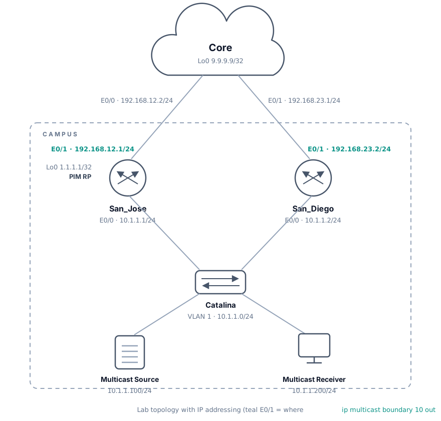
Lab topology with IP addressing (teal E0/1 = where ip multicast boundary 10 out is applied)
3.2 Image selection
| EVE node | Role | Recommended image | Notes |
|---|---|---|---|
| R1 | San_Jose (also RP) | IOL L3 (iol-x86_64) | Interface names are literally Ethernet0/0, matching the book |
| R2 | San_Diego | IOL L3 | |
| R3 | Core | IOL L3 | |
| R4 | Multicast Source | IOL L3 | |
| R5 | Multicast Receiver | IOL L3 | |
| SW | Catalina | IOL L2 (ioll2-x86_64) | All ports forwarding by default; no config needed |
vIOS / vIOS-L2 work just as well — replace Ethernet with GigabitEthernet throughout the configs.
3.3 Cabling
| From | To |
|---|---|
| R1 e0/0 | SW p1 |
| R2 e0/0 | SW p2 |
| R3 e0/0 | R1 e0/1 |
| R3 e0/1 | R2 e0/1 |
| R4 e0/0 | SW p3 |
| R5 e0/0 | SW p4 |
3.4 Addressing plan
| Node | Interface | IP | Notes |
|---|---|---|---|
| San_Jose | Lo0 | 1.1.1.1/32 | PIM RP |
| San_Jose | E0/0 | 10.1.1.1/24 | campus LAN |
| San_Jose | E0/1 | 192.168.12.1/24 | boundary out |
| San_Diego | E0/0 | 10.1.1.2/24 | campus LAN |
| San_Diego | E0/1 | 192.168.23.2/24 | boundary out |
| Core | E0/0 | 192.168.12.2/24 | — |
| Core | E0/1 | 192.168.23.1/24 | — |
| Core | Lo0 | 9.9.9.9/32 | IGMP join — emulates a core-side receiver |
| Catalina | VLAN 1 | 10.1.1.0/24 | L2 only, no IP |
| Multicast Source | E0/0 | 10.1.1.100/24 | sends the multicast pings |
| Multicast Receiver | E0/0 | 10.1.1.200/24 | IGMP join, both test groups |
Test group addresses: 239.65.10.10 and 239.193.10.10 (the two groups given in the exercise).
4 Complete Node Configurations
R1 — San_Jose (also the RP)
hostname San_Jose
!
ip multicast-routing
!
interface Loopback0
 ip address 1.1.1.1 255.255.255.255
 ip pim sparse-mode
!
interface Ethernet0/0
 ip address 10.1.1.1 255.255.255.0
 ip pim sparse-mode
 no shutdown
!
interface Ethernet0/1
 ip address 192.168.12.1 255.255.255.0
 ip pim sparse-mode
 no shutdown
!
router ospf 1
 network 0.0.0.0 255.255.255.255 area 0
!
ip pim rp-address 1.1.1.1
R2 — San_Diego
hostname San_Diego
!
ip multicast-routing
!
interface Ethernet0/0
 ip address 10.1.1.2 255.255.255.0
 ip pim sparse-mode
 no shutdown
!
interface Ethernet0/1
 ip address 192.168.23.2 255.255.255.0
 ip pim sparse-mode
 no shutdown
!
router ospf 1
 network 0.0.0.0 255.255.255.255 area 0
!
ip pim rp-address 1.1.1.1
R3 — Core (Loopback join = emulates a receiver in the core)
hostname Core
!
ip multicast-routing
!
interface Loopback0
 ip address 9.9.9.9 255.255.255.255
 ip pim sparse-mode
 ip igmp join-group 239.65.10.10
 ip igmp join-group 239.193.10.10
!
interface Ethernet0/0
 ip address 192.168.12.2 255.255.255.0
 ip pim sparse-mode
 no shutdown
!
interface Ethernet0/1
 ip address 192.168.23.1 255.255.255.0
 ip pim sparse-mode
 no shutdown
!
router ospf 1
 network 0.0.0.0 255.255.255.255 area 0
!
ip pim rp-address 1.1.1.1
R4 — Multicast Source (plain unicast node, no multicast config)
hostname Multicast-Source
!
interface Ethernet0/0
 ip address 10.1.1.100 255.255.255.0
 no shutdown
R5 — Multicast Receiver
hostname Multicast-Receiver
!
ip multicast-routing
!
interface Ethernet0/0
 ip address 10.1.1.200 255.255.255.0
 ip pim sparse-mode
 ip igmp join-group 239.65.10.10
 ip igmp join-group 239.193.10.10
 no shutdown
!
ip pim rp-address 1.1.1.1
SW — Catalina
On IOL L2 every port ships in VLAN 1 and up — no configuration needed; just confirm the ports are up:
show interfaces status5 Lab Procedure (Three Acts) and Verification
Act 1 Without the boundary: reproduce the leak
- Send traffic from the source (multicast pings standing in for the application):
Multicast-Source# ping 239.65.10.10 source e0/0 repeat 9999 timeout 1
Multicast-Source# ping 239.193.10.10 source e0/0 repeat 9999 timeout 1-
Expected result: the receiver and the core’s loopback both answer. — That is precisely the behavior the exercise asks us to prevent: the traffic has reached the core.
-
Confirm on R1 that forwarding state was built toward the core:
San_Jose# show ip mroute 239.65.10.10
(*, 239.65.10.10), ...
  Incoming interface: Ethernet0/0 (RPF)
  Outgoing interface list:
    Ethernet0/1, Forward/Sparse, ...   <-- state built toward the core
Act 2 Apply the boundary (the solution)
- Configure on both R1 and R2:
access-list 10 deny 239.65.10.10
access-list 10 deny 239.193.10.10
access-list 10 permit any
!
interface Ethernet0/1
ip multicast boundary 10 out- Clear state to speed convergence, then retest:
San_Jose# clear ip mroute *- Expected results:
| Check | Command / action | Expected |
|---|---|---|
| Receiver still receives | re-run the multicast ping | replies as before |
| Core receives nothing | same | no replies |
| OIF disappears | show ip mroute 239.65.10.10 |
E0/1 no longer in the outgoing list |
| ACL hit counter climbs | show access-lists 10 |
matches increase on the deny lines |
| Boundary confirmed active | show ip multicast boundary |
ACL 10 listed on E0/1 |
Act 3 (optional) Contrast with TTL scoping
- Remove the boundary and substitute on R1 / R2 E0/1:
interface Ethernet0/1
ip multicast ttl-threshold 15- IOS ping cannot set a custom TTL, so the easiest source is a Linux Docker node attached to Catalina, addressed
10.1.1.100/24:
ping -t 10 239.65.10.10    # TTL=10 < 15 -> cannot leave the campus
ping -t 20 239.65.10.10    # TTL=20 > 15 -> reaches the core
The conclusion becomes visible: for the very same group, whether traffic crosses the boundary depends on the TTL chosen by whoever sends it — direct evidence of why TTL scoping is application-dependent and imprecise compared to the boundary.
6 Troubleshooting Notes
| Symptom | What to check, in order |
|---|---|
| Receiver receives nothing at all | show ip igmp groups (is R5 in the group?) → show ip pim neighbor (are all three routers full?) → show ip pim rp mapping (is RP info consistent?) |
| The core should receive but doesn’t | show ip mroute — does Core have (*,G) and an OIF? Check ip igmp join-group on Core Lo0 |
| Boundary configured, yet the core still receives | Confirm it is on E0/1 (the core-facing port) with the out direction; retest after clear ip mroute *; check that matches climb on show access-lists 10 |
| RPF failure | show ip rpf 10.1.1.100; confirm the OSPF adjacencies are full |
Key mechanism: with
out, the boundary filters outbound data and control packets — PIM joins are stopped, so no state is ever built toward the core. That is what makes the boundary smarter than a TTL threshold: it doesn’t just drop data, it prevents the state from existing.
7 One-Page Summary
- What’s tested: multicast scoping — TTL scoping vs administrative scoping.
- The solution:
ip multicast boundary <ACL> outon the campus exit interfaces (E0/1 on both border routers) — per-group filtering, enforced on both the control plane and the data plane. - Part (b): 239.65.10.10 lands in the reserved 239.64.0.0/10 block; 239.193.10.10 sits in organization-local (239.192.0.0/14) and is fine; the two addresses straddle scope blocks, so no single standard boundary covers both — pick both groups from 239.192.0.0/14 instead.
- Lab essence: join the groups on Core Lo0 to watch the leak → apply the boundary and watch the core go silent while the campus keeps working → (optional) TTL threshold + Linux
ping -tto show why TTL scoping is unreliable.